
Laser Powder Bed Fusion (LPBF) has become one of the most widely adopted metal additive manufacturing processes for producing complex, high-performance components. From aerospace and defense to medical and energy applications, the technology enables geometries that would be difficult or impossible to manufacture conventionally.
Yet despite its advantages, defect formation remains one of the biggest challenges in LPBF production.
Porosity, lack-of-fusion defects, cracking, residual stress, distortion, and surface anomalies can all affect part quality, mechanical performance, and qualification outcomes. In many cases, these defects are only discovered after a build is complete, when significant time, material, and machine resources have already been invested.
The challenge is not simply detecting defects. It is understanding how they form, what process conditions create them, and whether they could have been identified earlier.
Recent research has shown that many critical LPBF defects originate from measurable process anomalies that occur during the build itself. Powder bed disturbances, spatter accumulation, part protrusions, recoater interactions, and local topography changes can all act as early indicators of instability before a defect becomes embedded within a finished component [1].
This article explores the most common defects in Laser Powder Bed Fusion, the mechanisms that cause them, the inspection methods used to identify them, and the strategies manufacturers use to prevent them.
Why Defects Occur in Laser Powder Bed Fusion
Laser Powder Bed Fusion builds metal parts one layer at a time. A thin layer of metal powder is spread across the build platform. A laser selectively melts regions of that powder according to the part geometry. The platform then lowers, a new layer of powder is applied, and the process repeats until the component is complete.
Although the process appears straightforward, the physics are highly dynamic.
Each laser pass creates a localized melt pool that forms, moves, solidifies, cools, and may later be reheated by neighbouring scan tracks or subsequent layers. The material experiences steep thermal gradients, rapid solidification, repeated thermal cycling, and geometry-dependent heat flow. These conditions are central to both the capabilities and the risks of LPBF.
Defect formation is rarely caused by a single parameter. Instead, defects typically emerge from interactions between laser power, scan speed, hatch spacing, layer thickness, beam focus, powder quality, shielding gas flow, recoater behavior, scan strategy, support design, part geometry, material chemistry, and thermal history [1].
This is why LPBF quality is often described as a process window rather than a single optimal parameter set.
A parameter combination that produces dense material in one geometry may generate defects in another. Thin walls, overhangs, internal channels, large cross-sections, and support-constrained regions all change local heat flow. Powder spreading can also vary across the build plate, and small disturbances at one layer may influence melting behavior several layers later.
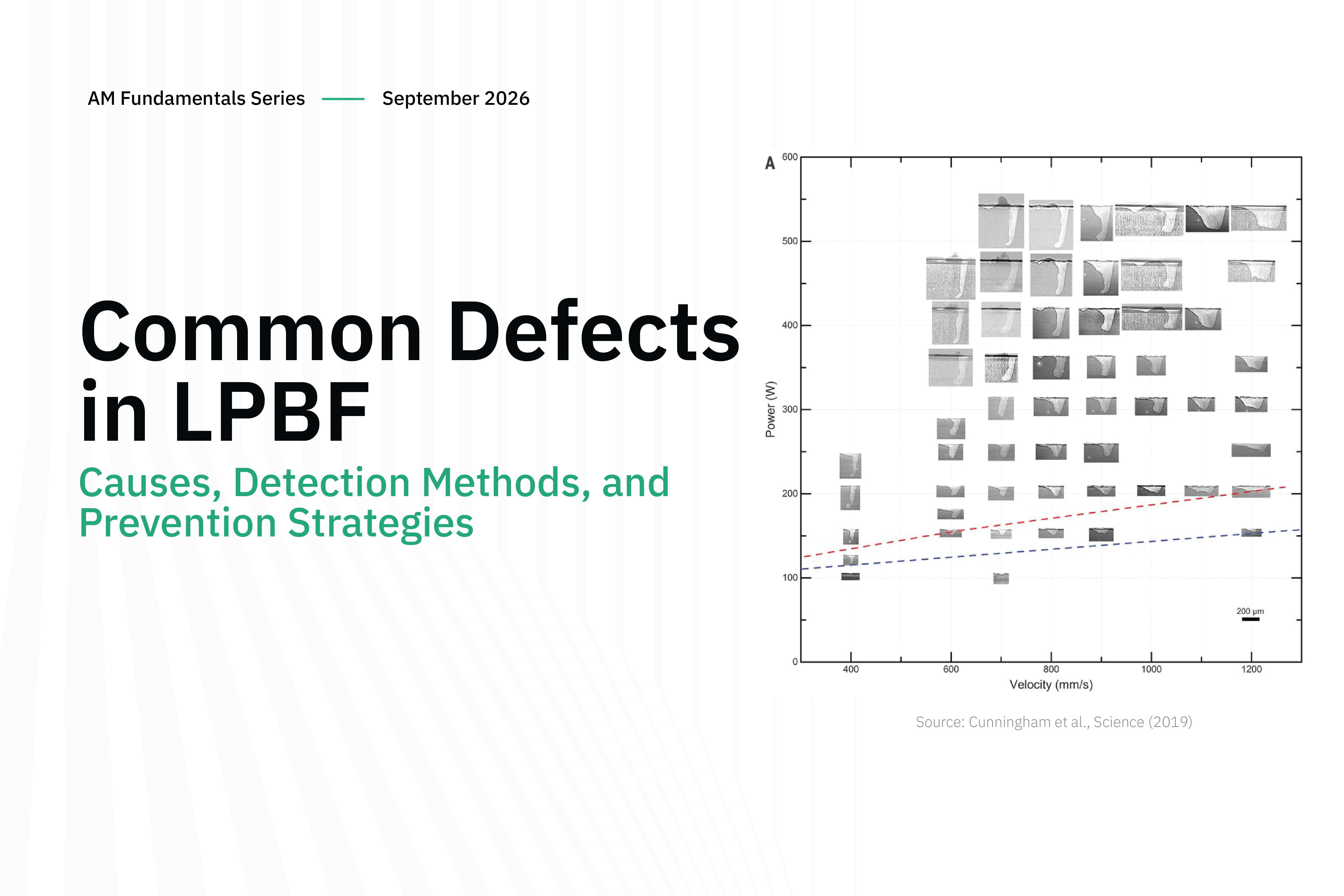
This also explains why volumetric energy density, or VED, should be treated carefully. VED is useful as a screening concept, but it does not fully describe melt pool stability. Two parameter sets can have the same VED while producing different melt pool shapes, pore morphologies, surface roughness, and bonding behavior [1].
For manufacturers, the implication is simple: defect prevention depends on controlling the full LPBF process, not simply increasing energy input or relying on a single density measurement.
Laser Powder Bed Fusion builds metal parts one layer at a time. A thin layer of metal powder is spread across the build platform. A laser selectively melts regions of that powder according to the part geometry. The platform then lowers, a new layer of powder is applied, and the process repeats until the component is complete.
Although the process appears straightforward, the physics are highly dynamic.
Each laser pass creates a localized melt pool that forms, moves, solidifies, cools, and may later be reheated by neighbouring scan tracks or subsequent layers. The material experiences steep thermal gradients, rapid solidification, repeated thermal cycling, and geometry-dependent heat flow. These conditions are central to both the capabilities and the risks of LPBF.
Defect formation is rarely caused by a single parameter. Instead, defects typically emerge from interactions between laser power, scan speed, hatch spacing, layer thickness, beam focus, powder quality, shielding gas flow, recoater behavior, scan strategy, support design, part geometry, material chemistry, and thermal history [1].
This is why LPBF quality is often described as a process window rather than a single optimal parameter set.
A parameter combination that produces dense material in one geometry may generate defects in another. Thin walls, overhangs, internal channels, large cross-sections, and support-constrained regions all change local heat flow. Powder spreading can also vary across the build plate, and small disturbances at one layer may influence melting behavior several layers later.
This also explains why volumetric energy density, or VED, should be treated carefully. VED is useful as a screening concept, but it does not fully describe melt pool stability. Two parameter sets can have the same VED while producing different melt pool shapes, pore morphologies, surface roughness, and bonding behavior [1].
For manufacturers, the implication is simple: defect prevention depends on controlling the full LPBF process, not simply increasing energy input or relying on a single density measurement.
The Most Common LPBF Defects
The most common LPBF defects can be grouped into several major categories:
- Porosity
- Keyhole defects
- Lack-of-fusion defects
- Gas pores
- Cracking
- Residual stress and distortion
- Delamination
- Surface roughness
- Balling
- Spatter
- Powder bed defects
- Contamination and inclusions
- Microstructural anomalies
Each defect type has different root causes, inspection requirements, and effects on part performance. Some defects are internal and may only be visible through CT scanning or metallographic sectioning. Others first appear at the layer surface, where they may be detected during the build.
This distinction matters. In production additive manufacturing, the most valuable information is often not the final defect alone, but the process signature that preceded it.

LPBF Porosity
Porosity is one of the most important defect categories in metal additive manufacturing. Pores are voids inside the printed part. Depending on their size, shape, location, and distribution, they can reduce density, weaken mechanical properties, and significantly affect fatigue life.
However, LPBF porosity is not a single defect mechanism. The three most common types are keyhole porosity, lack-of-fusion porosity, and gas porosity [1].
Each type has a different morphology and a different root cause. That means the corrective action is different too. Treating all porosity as one problem can lead to ineffective process changes.
Keyhole Porosity
Keyhole porosity is associated with unstable vapor depression formation within the melt pool under high energy density conditions. When the keyhole becomes unstable and collapses, voids can become trapped within the solidifying material [2].

Keyhole-induced bubble and pore development during LPBF. Source: Huang et al., “Keyhole fluctuation and pore formation mechanisms during laser powder bed fusion additive manufacturing”, 2022, Figure 4. Licensed under CC BY 4.0.
Keyhole pores are usually rounded or near-spherical. They often form below the surface and may appear in clusters depending on process conditions.
Common causes of keyhole porosity include excessive laser power, low scan speed, high power density, incorrect beam focus, excessive heat accumulation, and unstable melt pool dynamics.
A key lesson for LPBF process optimization is that more energy is not always better. Increasing energy input can reduce lack-of-fusion defects up to a point, but beyond the stable processing window it can drive the melt pool into an unstable keyhole regime. High-speed X-ray imaging studies have shown how keyhole instability and collapse can generate pores during laser melting [2].
For production teams, this makes keyhole porosity a process-control issue. It is not enough to target high density. The process must remain stable across the full part geometry and throughout the build.
Lack-of-Fusion Defects
Lack-of-fusion defects occur when powder or previously solidified material does not fully melt and bond with surrounding material. These defects are often irregular, elongated, or crack-like in shape. They may appear at hatch boundaries, layer boundaries, or regions where melt pool overlap is insufficient.
Common causes of lack-of-fusion defects include insufficient laser power, excessive scan speed, large hatch spacing, excessive layer thickness, poor powder spreading, rough previous layers, inadequate overlap between scan tracks, and challenging overhang or downskin conditions [1].
Lack-of-fusion porosity is especially concerning because the defects can be sharp or elongated. This makes them more damaging to fatigue performance than small spherical gas pores. Their geometry can concentrate stress and create preferred sites for crack initiation.

SEM images of lack-of-fusion pores in LPBF 316L. Source: Yazdanpanah et al., “Correlation of Lack of Fusion Pores with Stress Corrosion Cracking Susceptibility of L-PBF 316L”, 2022, Figure 2. Licensed under CC BY 4.0.
In practical terms, lack of fusion often indicates that the local process conditions did not provide enough effective melting. This may be due to parameter selection, but it may also result from local powder bed disturbance, part geometry, or previous layer roughness.
This is one reason layer-by-layer inspection is valuable. A powder bed disturbance or surface anomaly may appear before the lack-of-fusion defect becomes buried inside the part.
Gas Porosity
Gas porosity refers to spherical pores caused by trapped gas. Some gas pores originate in the metal powder itself, especially if gas becomes trapped during atomization. Others form when shielding gas or vapor becomes trapped during melting and solidification.
Gas porosity is generally associated with entrapped gas originating from powder feedstock, shielding gas interactions, or gas retention during melt pool solidification [9]. Powder quality and handling practices can influence the likelihood of these defects occurring.

Optical and SEM analysis of pore morphology in LPBF 316L. Source: Yazdanpanah et al., “Correlation of Lack of Fusion Pores with Stress Corrosion Cracking Susceptibility of L-PBF 316L”, 2022, Figure 1. Licensed under CC BY 4.0
Gas pores are often smoother and more spherical than lack-of-fusion defects. Their effect on part performance depends on their size, number, distribution, and location.
Although gas porosity is sometimes less severe than irregular lack-of-fusion defects, it still matters for fatigue-critical and pressure-containing applications. It also highlights a broader point: not all LPBF defects originate during laser scanning. Powder quality, handling, storage, and reuse practices are part of the defect-control system.
Cracking in LPBF
Cracking is another major defect category in Laser Powder Bed Fusion, especially for crack-sensitive alloys. Cracks can form during solidification, cooling, reheating, or post-build thermal exposure.
Common types of LPBF cracking include solidification cracking, hot tearing, liquation cracking, stress-assisted cracking, and interlayer cracking.
Cracking is strongly material dependent. Some alloys are highly printable, while others are more susceptible because of their chemistry, freezing range, grain structure, or segregation behavior.
High-strength aluminum alloys, for example, may experience solidification cracking because they have wide freezing ranges and are vulnerable to hot tearing. Nickel superalloys can develop cracking risks linked to segregation and secondary phases. Titanium alloys are generally less susceptible to solidification cracking than many aluminum alloys, although residual stress accumulation and microstructural evolution remain important process considerations [9].

Crack formation in an LPBF-built metal specimen. Image: Phase3D.
Cracks are particularly serious because they can act as sharp stress concentrators. Unlike small spherical pores, cracks can rapidly reduce fatigue life and fracture resistance. Detecting cracks may require CT scanning, metallography, microscopy, or other nondestructive testing methods depending on size, orientation, and location.
Residual Stress and Distortion
Residual stress is one of the defining challenges of LPBF.
Because the process repeatedly heats and cools small regions of material, the part develops internal stress as it grows. The build plate, supports, surrounding material, and geometry all constrain thermal expansion and contraction.
Residual stress can lead to warping, curling, part distortion, support failure, dimensional inaccuracy, recoater strikes, cracking, and delamination [1].
Distortion is especially problematic because it affects both part quality and build stability. A region that curls upward may interfere with the recoater, creating streaks, powder spreading problems, surface damage, or even build interruption.
Residual stress is not only a material problem. It is also a design, support, scan strategy, and thermal management problem. Part orientation, support structure, island scanning, contour strategies, preheating, and stress-relief heat treatment can all influence the final stress state.
For production LPBF, controlling distortion is essential for dimensional accuracy, repeatability, and build reliability.
Delamination
Delamination occurs when layers separate from each other or from support structures. It may result from inadequate fusion, stress-driven layer separation, residual stress accumulation, warping, or recoater interactions [9].

Distortion and delamination during LPBF manufacturing leading to process failure. Source: “Residual Stress Formation Mechanisms in Laser Powder Bed Fusion - A Numerical Evaluation”, 2023, Figure 1. Licensed under CC BY 4.0.
In severe cases, delamination can cause a build to fail before completion. Even when the build finishes, layer separation can make a part unusable.
Delamination is often connected to earlier process signals. A surface may begin to lift. A recoater may leave a streak. A region may show abnormal roughness or height variation. These layer-level anomalies can indicate that structural integrity is already at risk.
For this reason, delamination is not only a final part defect. It is also part of a wider build stability problem, where geometry, stress, fusion quality, recoater clearance, and surface condition interact.
Surface Defects in LPBF: The First Visible Signs of Process Instability
While porosity and cracking often receive the most attention in additive manufacturing, many critical defects begin much earlier in the build process.
Before a pore forms inside a component or a crack propagates through a load-bearing region, the process often produces visible anomalies at the layer surface. These defects may initially appear to be cosmetic, but they frequently provide the earliest evidence that the build is drifting away from stable operating conditions.
For manufacturers focused on quality assurance, these surface signatures are increasingly important because they can be measured during production rather than after the part is complete.
The most common surface-related defects in LPBF include:
- Surface roughness
- Balling
- Spatter
- Powder bed disturbances
- Recoater streaks
- Part protrusions
- Part uplift
- Layer non-uniformity
Individually, these issues may not always cause part failure. Collectively, however, they can influence melt pool behavior, interlayer bonding, dimensional accuracy, and ultimately the structural integrity of the finished component.
Surface Roughness
Surface roughness is one of the most visible and widely studied quality characteristics in Laser Powder Bed Fusion [9].
As-built LPBF surfaces rarely emerge with the same finish quality achieved through conventional machining. Instead, they often exhibit partially melted particles, stair-stepping effects, waviness, adhered powder, contour irregularities, and downskin dross.
Surface roughness is influenced by numerous process variables, including:
- Build orientation
- Layer thickness
- Powder particle size distribution
- Laser parameters
- Scan strategy
- Material properties
- Support design
- Downskin settings
Historically, roughness has sometimes been viewed primarily as a finishing issue. However, research increasingly shows that rough surfaces can have significant performance implications.

Surface roughness on LPBF-built test components. Image courtesy of Phase3D.
Surface roughness can:
- Increase stress concentration
- Reduce fatigue life
- Influence fluid flow
- Affect sealing performance
- Increase powder retention
- Complicate support removal
- Increase post-processing requirements
In fatigue-critical applications, surface-connected defects are often more damaging than internal pores because they are directly exposed to applied loading. A part may exhibit excellent density while still requiring extensive machining or finishing to achieve acceptable fatigue performance.
Surface roughness is therefore not merely a cosmetic characteristic. It is an important quality metric that often reflects the underlying stability of the LPBF process.
Balling
Balling occurs when a molten track fails to remain continuous and instead breaks into discrete beads or droplets.
Rather than forming a smooth weld track, the material separates into a series of spherical accumulations along the scan path. The resulting surface appears irregular and discontinuous.
Balling is generally associated with:
- Poor wettability
- Excessive scan speed
- Insufficient energy input
- Surface tension effects
- Oxidation
- Melt pool instability
- Unfavorable thermal conditions [9]
The defect is particularly important because it connects fundamental melt pool physics to broader manufacturing outcomes.
 Balling and discontinuous melt-track formation during selective laser melting of magnesium alloy. Source: “Balling Behavior of Selective Laser Melting Magnesium Alloy”, 2020, Figure 3. Licensed under CC BY 4.0.
A balling event may initially appear as a localized surface defect. However, discontinuous melt tracks can reduce interlayer bonding, increase roughness, create local geometry variation, and contribute to future lack-of-fusion defects.
For this reason, balling is often considered one of the clearest examples of how small process instabilities can propagate into larger quality problems.
Spatter
Spatter is one of the most widely observed process phenomena in Laser Powder Bed Fusion [10].
During laser processing, molten or partially molten particles can be ejected from the melt pool due to recoil pressure, vapor plume interactions, keyhole dynamics, and turbulent melt flow.
These particles may travel significant distances before landing elsewhere on the powder bed.
Common causes of spatter include:
- High laser power
- Keyhole instability
- Vapor plume dynamics
- Recoil pressure
- Melt pool turbulence
- Gas flow interactions
- Multi-laser interference
Spatter is particularly important because it functions as both a symptom and a cause of instability.

Spatter generation during LPBF processing. Image courtesy of Phase3D.
On one hand, excessive spatter can indicate unstable melt pool conditions. On the other, redeposited particles can create new process challenges by disturbing powder spreading, increasing roughness, creating local height variations, or altering subsequent laser-material interactions [10].
Recent studies have demonstrated direct relationships between spatter behavior and layer surface roughness, highlighting the growing importance of surface inspection in identifying developing process issues before they become buried defects [6].
Powder Bed Defects
Every LPBF layer begins with powder deposition.
If the powder layer is inconsistent, contaminated, streaked, or disturbed, the subsequent melting process is unlikely to proceed as intended.
Powder bed quality is increasingly recognised as a critical contributor to LPBF quality and process stability [9].
Common powder bed defects include:
- Recoater streaks
- Missing powder regions
- Excess powder accumulation
- Powder pile-up
- Dragged particles
- Surface debris
- Uneven spreading
- Powder contamination
 Powder distribution during LPBF showing (a) correct powder distribution, (b) super-elevation, (c) recoater damage, and (d) recoater vibration. Source: Korzeniowski et al., “Development and Implementation of a Deep Learning Algorithm to Evaluate the Powder Distribution Process During 3D Printing Using the LPBF Method”, 2024, Figure 1. Licensed under CC BY 4.0
These defects can influence local energy absorption, melt pool shape, thermal behavior, and track continuity.
Importantly, powder bed defects occur before melting.
This means they can often be detected and measured before they create downstream quality issues. A disturbed powder region may eventually lead to lack-of-fusion porosity, dimensional deviation, poor surface finish, or even build interruption.
From an inspection perspective, powder bed quality represents one of the earliest opportunities for intervention.
Part Protrusions and Recoater Interactions
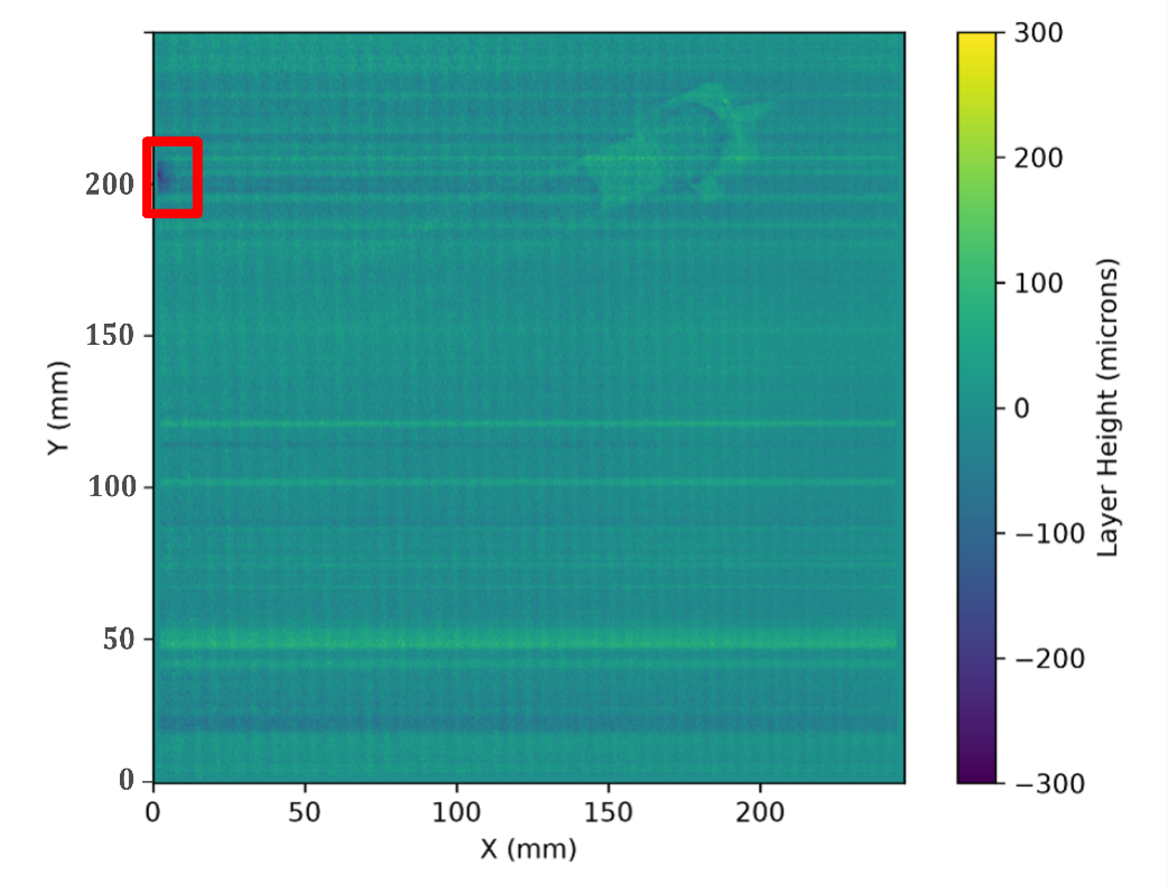
Part protrusions are another common precursor to more serious LPBF defects. A protrusion can arise through several mechanisms, including residual-stress-driven part uplift, local material accumulation, or other geometric deviations that extend above the expected layer height. Regardless of the cause, even relatively small protrusions can reduce clearance between the part and the recoater.
This can create:
- Surface damage
- Recoater streaking
- Powder redistribution
- Layer inconsistency
- Delamination
- Build interruption
In severe cases, recoater collisions can terminate a build entirely.

Fringe Inspection layer data showing a part protrusion developing across successive layers of an LPBF build.
What makes a part protrusion particularly important is that it often develops gradually. Small geometric changes may be visible several layers before catastrophic failure occurs.
This makes part protrusions an ideal target for layerwise inspection and topographical measurement.
How LPBF Defects Are Detected
No single inspection technology can identify every defect in additive manufacturing.
Different defect classes require different measurement approaches.
The most common LPBF inspection methods include:
- X-ray computed tomography (CT)
- Optical microscopy
- Metallography
- Scanning electron microscopy (SEM)
- Density measurement
- Surface profilometry
- Residual stress analysis
- In-situ process monitoring
- Layer-by-layer inspection
As additive manufacturing moves toward production-scale deployment, manufacturers increasingly combine multiple inspection techniques to create a more complete understanding of part quality.
CT Scanning for Additive Manufacturing
X-ray CT remains one of the most widely accepted methods for detecting internal defects in LPBF components [3].
Like all inspection methods, CT performance depends on scan resolution, part geometry, material density, and defect size, meaning very small defects may not always be detectable in production environments [3].
Unlike traditional radiography, CT provides three-dimensional information about internal features without sectioning the part.
CT inspection can identify:
- Internal porosity
- Lack-of-fusion defects
- Crack-like voids
- Defect clusters
- Internal geometry variation
- Defect size and location
This makes CT particularly valuable for qualification and root-cause investigations.
However, CT also has practical limitations. Scan times, equipment costs, resolution requirements, and part size constraints can make comprehensive CT inspection challenging for high-volume production environments. For this reason, manufacturers increasingly view CT as part of a broader quality workflow rather than a standalone solution.
Optical Microscopy, Metallography, and SEM
Microscopy remains essential for understanding defect morphology.
Cross-sectioning and metallographic preparation allow engineers to directly observe:
- Crack paths
- Unmelted particles
- Lack-of-fusion features
- Microstructure
- Inclusion content
- Phase distribution
- Internal Porosity
Scanning Electron Microscopy (SEM) provides additional resolution and can support compositional analysis through energy dispersive spectroscopy (EDS).
Although these methods are generally destructive, they remain among the most powerful tools available for defect investigation and material characterization.
Density Measurement
Archimedes density testing is commonly used as a rapid screening method.
Density measurements can help identify whether a build is achieving acceptable consolidation, but they provide limited insight into defect morphology.
A density value alone cannot distinguish between gas pores, keyhole porosity, lack-of-fusion defects, or cracking.
As a result, density measurements are most valuable when combined with complementary inspection techniques.
In-Situ Inspection and Process Monitoring
The most significant development in additive manufacturing quality assurance over the last decade has been the growth of in-situ inspection technologies [5].
Traditional quality workflows identify defects after production.
In-situ inspection seeks to identify process anomalies while the build is still in progress.
Common in-situ monitoring technologies include:
- Optical imaging
- Thermal imaging
- Melt pool monitoring
- Acoustic sensing
- Photodiode monitoring
- Machine sensor data
Each technology provides different insights into process behavior.
Thermal systems can reveal heat accumulation and melt pool dynamics. Acoustic approaches may identify keyhole instability. Optical systems can detect visible layer-level anomalies and powder bed defects [5].
The ultimate goal is not simply to record process data.
It is to understand which process signatures correlate with final part quality.
ASTM E3353 increasingly frames in-process monitoring as both an inspection tool and a statistical process control method for additive manufacturing production environments [4].
Why Layer-by-Layer Inspection Matters
Many of the defects that ultimately determine part acceptance begin as small changes at the layer surface [5].
A protrusion may indicate developing distortion. A powder streak may contribute to lack-of-fusion porosity. Spatter accumulation may alter local roughness and thermal behavior. Part protrusions may signal increasing residual stress.
By the time these issues appear in a CT scan, they have already become embedded within the component.
Layer-by-layer inspection provides an opportunity to identify these signatures when they first emerge.
Rather than asking whether a defect exists after the build is complete, manufacturers can begin asking whether the process is behaving as expected while the part is still being produced.
Layerwise Topography and Fringe Inspection®
One of the challenges in additive manufacturing inspection is that many defect precursors first appear as changes in surface geometry rather than as immediately detectable internal defects.
Before porosity, cracking, or delamination become visible through CT inspection, the process often produces measurable layer-level anomalies including:
- Powder bed disturbances
- Part protrusions
- Part uplift
- Recoater streaks
- Balling
- Local roughness changes
- Spatter accumulation [5]
These features alter the topology of the layer surface and may indicate that the process is drifting away from stable operating conditions.
Structured-light and fringe projection technologies provide a method for measuring these geometric changes with high resolution during the build process.
Unlike systems that focus exclusively on melt pool behavior, fringe projection systems directly measure the physical geometry of each completed layer.
Phase3D's Fringe Inspection® technology uses structured light projection and high-resolution topographical measurement to quantify layer geometry throughout the build process. This enables manufacturers to identify deviations such as protrusions, recoater interactions, powder bed irregularities, and localized height changes before they become buried within the finished part.
The value of layerwise topography inspection lies in its ability to identify process signatures rather than simply final defects.
A protrusion detected on one layer may eventually contribute to lack-of-fusion porosity, dimensional deviation, recoater contact, or build failure several layers later. Detecting the anomaly when it first appears provides a significantly larger opportunity for investigation and corrective action.
Recent research has also demonstrated a relationship between spatter behavior and layer surface roughness, further supporting the value of layerwise geometric inspection as a source of process intelligence [6].
As additive manufacturing quality systems continue to mature, the combination of layerwise geometric inspection, process monitoring, and post-build validation is becoming increasingly important for understanding the relationship between process behavior and final part quality [4,5].
How Manufacturers Prevent LPBF Defects
Preventing defects in Laser Powder Bed Fusion requires a layered quality strategy.
No single parameter, inspection method, or post-processing step can eliminate every defect type. Instead, successful LPBF production depends on controlling multiple variables across the entire manufacturing workflow, from powder qualification and machine setup through to inspection and post-build processing.
The most reliable additive manufacturing quality programs combine:
- Process parameter optimization
- Powder quality management
- Atmosphere control
- Support and build strategy optimization
- In-situ inspection
- Post-build validation
- Material-specific process development
As additive manufacturing moves from prototyping toward production, manufacturers are increasingly treating defect prevention as a systems problem rather than a machine parameter problem [7].
Process Parameter Optimization
The foundation of defect prevention is establishing a stable process window.
This involves identifying parameter combinations that consistently produce dense, repeatable material while avoiding both lack-of-fusion and keyhole regimes.
Key variables include:
- Laser power
- Scan speed
- Hatch spacing
- Layer thickness
- Beam focus
- Scan strategy
- Contour settings
- Downskin parameters
Historically, many LPBF discussions focused heavily on volumetric energy density (VED). While VED remains useful as a screening metric, it does not fully capture melt pool behavior.
Two parameter sets may have identical VED values while producing very different outcomes in terms of melt pool geometry, porosity, roughness, and dimensional stability [1].
For this reason, process development should focus on defect morphology and process stability rather than density alone.
Powder Quality Control
Powder quality is one of the most influential variables in LPBF production.
Even with optimized machine parameters, poor powder quality can introduce variability and increase defect risk.
Important powder characteristics include:
- Particle size distribution
- Morphology
- Flowability
- Chemistry
- Oxygen content
- Moisture exposure
- Contamination levels
- Reuse history
Powder degradation can occur gradually through repeated use. Particle morphology may change, oxygen content may increase, and spatter contamination may accumulate.
This is particularly important for oxygen-sensitive materials such as titanium and aluminum alloys.
Modern powder specifications increasingly require traceability, characterization, and controlled handling procedures to ensure consistency throughout production [8].
Atmosphere and Gas Flow Management
LPBF processing is typically performed under inert gas conditions to reduce oxidation and contamination.
However, atmosphere management influences more than chemistry.
Gas flow plays an important role in:
- Spatter removal
- Vapor extraction
- Thermal stability
- Powder bed cleanliness
- Melt pool behavior
Poor gas flow can allow spatter particles to redeposit on the build surface, increasing roughness and creating new defect opportunities [10].
As machine productivity increases and multi-laser systems become more common, gas flow design is becoming an increasingly important aspect of process stability.
Support Design and Build Strategy
Support structures perform several critical functions in LPBF.
They:
- Anchor the part
- Conduct heat
- Reduce distortion
- Resist residual stress
- Stabilize overhangs
However, support design is rarely straightforward.
Insufficient support may allow warping, delamination, overheating, or recoater interactions. Excessive support increases material consumption, post-processing effort, and production cost.
Build orientation also influences defect formation.
Orientation affects:
- Heat flow
- Surface roughness
- Support requirements
- Residual stress
- Recoater risk
- Dimensional accuracy
As a result, support strategy should be viewed as part of process optimization rather than simply a pre-processing step.
Post-Processing
Not every LPBF defect can be eliminated during printing.
Post-processing remains an essential component of additive manufacturing quality assurance.
Common post-processing approaches include:
- Stress relief heat treatment
- Hot isostatic pressing (HIP)
- Solution treatment
- Aging
- Machining
- Blasting
- Polishing
- Chemical finishing
Hot isostatic pressing is particularly effective at reducing the impact of internal porosity. However, HIP should not be viewed as a universal solution.
Cracks, inclusions, dimensional deviations, and surface-connected defects may still remain.
Similarly, heat treatment may improve microstructure and relieve stress, but it cannot compensate for fundamentally poor process control.
The most successful production workflows combine robust process control with targeted post-processing rather than relying on post-processing to repair manufacturing defects [7].
Defect Challenges by Material
Different LPBF materials exhibit different defect mechanisms.
A process strategy that performs well for one alloy may be unsuitable for another.
Understanding material-specific defect behavior is therefore essential for process qualification [9].
Ti-6Al-4V Defects
Ti-6Al-4V remains one of the most important LPBF materials due to its high strength-to-weight ratio, corrosion resistance, and aerospace and medical adoption.
Common LPBF defect concerns include:
- Porosity
- Residual stress
- Surface roughness
- Oxygen contamination
- Microstructural variability
Titanium's sensitivity to oxygen means powder quality and atmosphere control are especially important.
In addition, LPBF Ti-6Al-4V often forms a martensitic microstructure in the as-built condition. Heat treatment is frequently required to improve ductility and tailor final properties [9].
316L Stainless Steel Defects
316L is generally considered one of the more forgiving LPBF alloys.
Compared with many aluminum alloys and superalloys, cracking susceptibility is relatively low.
However, manufacturers still need to manage:
- Porosity
- Surface roughness
- Oxide inclusions
- Cellular microstructure
- Powder contamination
Because 316L is often used in qualification studies and process development programs, it provides a useful benchmark for understanding general LPBF defect behavior [9].
Inconel 718 Defects
Inconel 718 presents a different challenge.
While porosity control remains important, defect management extends beyond density.
LPBF Inconel 718 can develop:
- Porosity
- Segregation
- Laves phase formation
- Liquation cracking susceptibility
- Residual stress
- Distortion
As a result, successful production requires both defect control and microstructure control.
Heat treatment plays a particularly important role in achieving the required mechanical performance [9].
AlSi10Mg Defects
AlSi10Mg is one of the most widely adopted aluminum alloys for LPBF.
Compared with many higher-strength aluminum alloys, it exhibits relatively good printability.
However, manufacturers still face challenges including:
- Gas porosity
- Oxide-related defects
- Rough overhang surfaces
- Beam-focus sensitivity
- Powder quality variation
- Surface roughness
Because aluminum reflects laser energy more efficiently than many other metals, process stability often depends on careful control of optical conditions and powder characteristics [9].
Conclusion
Defects remain one of the biggest challenges in Laser Powder Bed Fusion, but they are rarely random events. Porosity, cracking, distortion, and delamination are typically the result of process conditions that develop over multiple layers.
As additive manufacturing moves toward production-scale adoption, the focus is shifting from finding defects after a build is complete to identifying the process signatures that precede them. Powder bed disturbances, spatter, part protrusions, recoater interactions, and layer-to-layer variation can all provide valuable insight into build quality before defects become embedded within a finished part.
The future of LPBF quality assurance will rely on connecting these in-process signals to final part performance. The earlier manufacturers can identify process instability, the greater their ability to improve repeatability, reduce scrap, and build confidence in additive manufacturing production.
Frequently Asked Questions
What is the most common defect in LPBF?
Porosity is generally considered the most significant internal defect in LPBF because of its impact on mechanical performance and fatigue life. The three primary categories are keyhole porosity, lack-of-fusion porosity, and gas porosity. Each forms through different mechanisms and has different implications for part performance.
What causes porosity in additive manufacturing?
Porosity can result from excessive energy input, insufficient melting, trapped gas, unstable keyhole behavior, poor powder quality, contamination, or powder bed disturbances. The specific cause depends on the pore morphology and process conditions.
More on that here.
What is a lack-of-fusion defect?
A lack-of-fusion defect occurs when neighboring melt tracks or layers fail to bond completely. These defects are often irregular and elongated and can significantly reduce fatigue performance.
Why is residual stress a problem in LPBF?
LPBF creates steep thermal gradients as material repeatedly heats and cools during processing. These thermal cycles generate internal stresses that may cause warping, distortion, cracking, delamination, or recoater interactions.
How are LPBF defects detected?
Common LPBF inspection methods include:
- X-ray CT scanning
- Optical microscopy
- SEM analysis
- Metallography
- Density measurement
- Surface profilometry
- In-situ monitoring
- Layer-by-layer inspection
Different methods are better suited to different defect classes.
What is in-situ inspection?
In-situ inspection refers to measuring build quality while the manufacturing process is taking place. Examples include optical imaging, thermal monitoring, melt pool monitoring, acoustic sensing, and layerwise topography measurement.
What is Fringe Inspection®?
Fringe Inspection® is a structured-light inspection technology developed by Phase3D that measures the geometry of each layer during an additive manufacturing build. By generating high-resolution topographical information, it can identify process anomalies such as protrusions, powder bed disturbances, uplift, recoater interactions, and localized geometry variation before they become buried within the finished component.
Can LPBF defects be prevented completely?
No manufacturing process is entirely defect-free. However, defect occurrence can be significantly reduced through robust process development, powder quality control, atmosphere management, inspection, and post-processing strategies.
The Future of LPBF Quality Assurance
As additive manufacturing scales from prototyping toward serial production, quality assurance is evolving alongside it.
Historically, manufacturers have relied heavily on post-build inspection to determine whether a part is acceptable. While these methods remain essential, they provide limited insight into when defects formed or how they developed.
The future of additive manufacturing quality assurance is increasingly focused on connecting process behavior to final part quality.
This means understanding not only what defects exist, but also:
- When they originated
- What conditions created them
- Whether they could have been detected earlier
- How they can be prevented in future builds
Many critical LPBF defects begin as measurable process signatures.
Powder bed disturbances, spatter accumulation, layer roughness variation, protrusions, part uplift, and recoater interactions may all provide early evidence that the process is drifting away from stability.
This is why layer-by-layer inspection is becoming increasingly important within advanced additive manufacturing workflows.
The combination of process monitoring, topographical inspection, CT validation, material characterization, and production analytics provides a more complete understanding of quality than any single inspection method alone.
Laser Powder Bed Fusion has already demonstrated its ability to manufacture highly complex, high-value components. The next phase of adoption will depend on making that production more predictable, repeatable, and easier to qualify.
Achieving that goal starts with understanding defects not as isolated failures, but as process signatures.
The earlier those signatures can be identified, measured, and understood, the greater the opportunity to improve quality, reduce scrap, and increase confidence in additive manufacturing production.
References:
[3] ASTM E1441 / ASTM E3166 – CT Inspection and NDT for Additive Manufacturing Parts
[4] ASTM E3353 – Additive Manufacturing Process Monitoring
[6] Zhang et al. (2023) – Influence of Spattering on In-Process Layer Surface Roughness During LPBF
[7] ISO/ASTM 52904 – Metal Powder Bed Fusion Process Characteristics and Performance
[8] ISO/ASTM 52907 – Feedstock Materials and Powder Characterization
[9] Mostafaei et al. (2022) – Defects and Anomalies in Powder Bed Fusion Metal Additive Manufacturing
Share: