
Part protrusion is one of the most costly failure modes in laser powder bed fusion (LPBF). Even a small amount of upward distortion can damage the recoater, disrupt the powder bed and cause multiple otherwise healthy parts to fail.
This case study demonstrates how Phase3D's Fringe Inspection™ detected a protruding titanium part before catastrophic failure occurred by measuring changes in powder bed height on every layer throughout the build.
Using quantitative height maps rather than image-based indicators, Fringe Inspection identified protrusion developing over approximately twelve layers, giving manufacturers an opportunity to intervene before recoater damage occurred.
Catching that signal early has a direct payoff. A part trending towards protrusion can be canceled before it takes down the parts around it or forces a build stoppage, and a build that is no longer worth finishing can be ended early rather than stop due to a failure that was already visible in the data. In both cases, machine time and material that would otherwise be lost can be preserved. Just as importantly, it gives manufacturers a way to act before a recoater collision, hop, or streak ever occurs – avoiding the cascading powder bed disturbances that a single protruding part can inflict on every other part sharing the build plate.
This case study examines a challenge build in which a cantilevered geometry, printed specifically to induce high residual stress, warped out of the powder bed and damaged the recoater badly enough to stop the remaining parts on the build from finishing. Using Fringe Inspection data captured during the print, Phase3D isolated the part of interest and quantified how far and how fast it rose out of the bed.
At a Glance
Industry
Metal Additive Manufacturing
Process
Laser Powder Bed Fusion (LPBF)
Material
Ti-6Al-4V
Machine
EOS M290
Challenge
Part protrusion caused by residual stress
Technology
Phase3D Fringe Inspection™
Outcome
- Protrusion detected before build failure
- ROI isolated automatically
- Measurable height increase from 15 µm to 986 µm
- Objective data for stop/go decisions
Key Findings
| Finding | Description |
| Early, Quantifiable Signal | Fringe Inspection detected that powder height over the part rose from a ~15 µm baseline to 112 µm, and maximum height rose from roughly 90 µm to 986 µm, over the final 12 measured layers before the build stopped. |
| Region-of-Interest Isolation | Powder thickness data was used to mask the cantilever geometry, isolating its height trend from the rest of the build plate on a layer-by-layer basis. |
| Rapid Escalation | Once the part began lifting, protrusion compounded quickly, climbing from a subtle deviation to a build-ending anomaly in about a dozen layers. |
| Recoater Damage | Fringe Inspection beyond raw height data detected recoater damage, halting every remaining part on the build before they finished printing. |
| Data-Driven Stop Decisions | Quantitative height trending gives manufacturers an objective basis for stopping a part or a build before recoater collision, obstruction, hopping, or streaking occurs. |
What Causes Part Protrusion in LPBF?
Part protrusion occurs when a printed component lifts above the intended powder bed surface during a laser powder bed fusion (LPBF) build. Even relatively small height increases can interfere with the recoater, resulting in powder bed disruption, poor layer quality and ultimately complete build failure.
It's a broad failure mode with several distinct root causes:
Thermal Distortion
- Warping, curling, and bowing driven by residual stress that accumulates as the part heats and cools layer after layer.
Support-Related
- Support failure, fracture, or detachment, which releases the geometry a support was holding down and lets it spring or drift upward.
Melt-Related
-
Swelling, part elevation, or edge elevation occurring during melting, pushing material above the powder bed plane even without a support issue.
Why Part Protrusion Causes Build Failures
Part protrusion is rarely an isolated cosmetic issue. It sets off a chain of anomalies and failure mechanisms that can compromise an entire build:
- Recoater Collision: The recoater blade directly contacts the elevated part.
- Recoater obstruction: The recoater is blocked from completing its pass by the protruding geometry.
- Recoater hops: The recoater jumps over the protrusion, leaving an uneven powder layer in its wake.
- Powder streaks: A recoater damaged by the collision drags streaks across the powder bed on subsequent layers.
The downstream impacts compound from there: build stoppage, outright build failure, an inconsistent powder bed that introduces porosity into otherwise healthy parts, physical damage to the recoater itself, and collateral damage to neighboring parts. A single protruding feature can take down an entire plate of otherwise good parts.

The Objective
The objective of this study was to determine whether Fringe Inspection could detect and measure part protrusion early and precisely enough to give operators a real decision window before it escalates into a build-stopping event.
Fringe Inspection generates height maps for every powder and melted layer, allowing users to track trends including:
- Melted area height
- Powder bed height on top of parts
- Layer thickness on top of parts
Beyond raw height data, Fringe Inspection detects, classifies, and measures the downstream anomalies that protrusion causes, including recoater streaks and recoater hops. Together, these measurements let manufacturers make data-driven decisions about when or whether to stop an individual part or an entire build, rather than relying on visual judgment or waiting for a build to fail outright. In practice, that translates to increased yield for high quality parts.
Experimental Setup: Detecting Part Protrusion in Titanium LPBF
A challenge build was printed with geometries specifically designed to protrude out of the powder bed from high residual stress buildup and warping.
| Machine |
EOS M290 Platform (AMCM) |
| Material | Ti-6-4 |
| Layer Thickness | 30 µm |
| Build Intent | Challenge geometries designed for increased residual stress and distortion out of the powder bed |
This case study focuses on one geometry from that build: a cantilevered beam connected to the build plate through a series of pyramid connectors. This part warped enough to damage the recoater, and the resulting damage stopped the remaining parts on the build from finishing. This specimen is indicative of design choices often necessary in the aerospace and defense industry.

Side view of part of interest

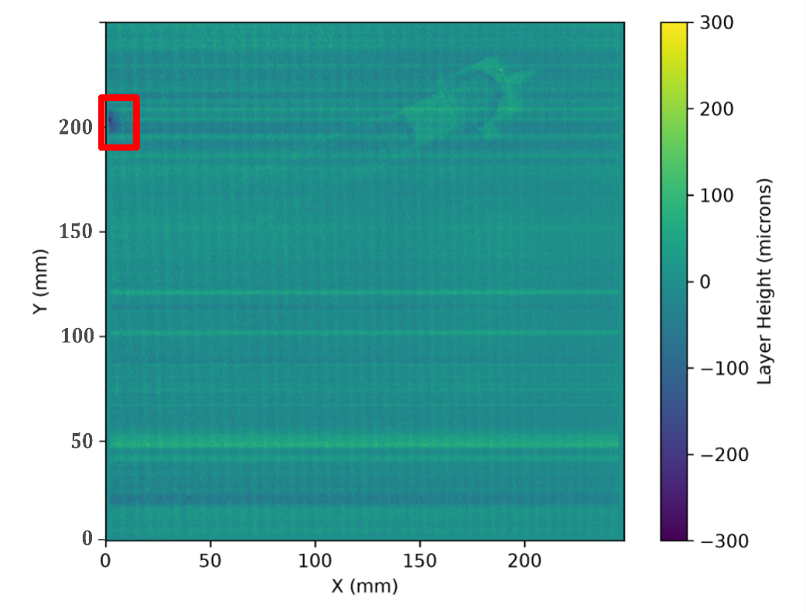
Powder heightmap (left) and layer thickness heightmap (right) at layer 484, showing the full build plate
How Fringe Inspection Measures Part Protrusion
Following the print, Phase3D analyzed the Fringe Inspection data to detect and quantify the part protrusion:
- Powder thickness measurements were used to define a region of interest (ROI) around the cantilevered beam geometry.
- The powder layers were masked so that only measurements from the part's ROI were analyzed, isolating its trend from the rest of the build.
- A layer range, layers 350 through 505, was selected to capture the trend in powder bed height over the cantilever beam as the build progressed.
- Two metrics were quantified for every layer in that range: mean powder height over the part, and maximum powder height over the part.

Magnified view of the powder heightmap, showing the area around the part of interest

Masked region defined on powder thickness heightmap
Results: Detecting Part Lift Before Recoater Failure
Two independent height metrics were analysed to determine whether protrusion could be identified before recoater failure occurred.
Layers 350 through 505 were analyzed to trend powder height over the cantilever beam's region of interest.

For roughly 140 layers, both metrics held steady: average height over the part area sat around 15 µm, and maximum height stayed under about 100 µm. This is consistent with normal powder recoating and well within the noise floor of the surrounding bed. Starting around layer 490, both metrics broke sharply from that baseline. By layer 505, average height over the part had risen to 112 µm and maximum height had reached 986 µm - a shift large enough, and fast enough, to be unmistakable against the build's own baseline.
Detecting Part Peel-Up, Layer by Layer
Zooming into measured layers shows the mechanism behind the trend: the beam is peeling up from the powder bed starting at the end nearest its pyramid connectors, then propagating outward. The deepening red region in the heightmaps below tracks that peel-up in real time, layer by layer, as both the average and maximum height over the part area climb.

The pattern is consistent with the warping mechanism this geometry was designed to induce: residual stress builds throughout the print, and once it overcomes the resistance of the pyramid connectors, the beam lifts away from the bed at an accelerating rate. What starts as a 15 µm deviation, comparable in scale to typical layer thickness, becomes a nearly 1 mm protrusion in the space of twelve layers.
Why Early Part Protrusion Detection Matters
Turning a Late-Build Failure Into an Early Decision Point
By the time the recoater was damaged, the height data had already shown a clear upward trend for approximately twelve layers. Rather than reacting to a mechanical failure, manufacturers could instead define engineering thresholds that identify problematic parts early enough to pause the build or remove the affected component before neighbouring parts are compromised.
Quantitative, Traceable Measurement Over Visual or AI-Based Flags
Fringe Inspection reports a height in microns, not a confidence score or a grayscale flag. That distinction matters when it's time to act: manufacturers can define objective, geometry-specific thresholds and trend data over time, instead of relying on operator judgment or an image with no engineering value attached to it. A measured 986 µm deviation is unambiguous in a way that a flagged pixel region is not.
Conclusion
Rather than identifying protrusion only after recoater damage has occurred, Fringe Inspection transforms part lift into a measurable process signal. By continuously tracking powder and melt layer height, manufacturers can establish quantitative intervention thresholds, prevent unnecessary machine damage and improve overall build yield. As build densities increase and geometries become more challenging, objective in-process metrology becomes increasingly important for reliable metal additive manufacturing.
→ Learn more about Fringe Inspection

Frequently Asked Questions
What is part protrusion in metal additive manufacturing?
Part protrusion occurs when a printed component, or a feature of that component, rises above the intended powder bed surface during a metal additive manufacturing build. In laser powder bed fusion (LPBF), protrusion is commonly caused by residual stress, support failure or melt-related deformation. If left unchecked, it can interfere with the recoater and lead to build failure.
What causes part protrusion during LPBF printing?
Several mechanisms can lead to part protrusion during laser powder bed fusion, including:
- Residual stress causing warping or curling
- Support structures breaking or detaching
- Thermal distortion during melting
- Edge elevation or material swelling
These mechanisms allow sections of the part to rise above the powder bed, increasing the risk of recoater interference.
Why is part protrusion a problem?
Part protrusion can have consequences beyond the affected component. A protruding feature can:
- Damage the recoater blade
- Cause recoater hops or collisions
- Create powder bed streaks and uneven layers
- Introduce defects into neighbouring parts
- Force the entire build to stop
Because multiple components often share a single build plate, one protruding part can jeopardise every part being manufactured.
How can part protrusion be detected?
Part protrusion can be detected by monitoring powder bed height throughout the build. Fringe Inspection™ generates quantitative height maps for every powder and melt layer, allowing manufacturers to identify subtle changes in part height before they become critical failures. Unlike image-only monitoring systems, Fringe Inspection measures actual height in microns.
Can part protrusion be detected before recoater damage occurs?
Yes. In this study, Fringe Inspection identified protrusion developing over approximately twelve measured layers before the recoater was damaged. Average powder height increased from approximately 15 µm to 112 µm, while maximum height increased to 986 µm, providing a measurable trend that could support earlier intervention.
How does Fringe Inspection measure part protrusion?
Fringe Inspection captures high-resolution height measurements after every powder and melt layer. Using these measurements, manufacturers can isolate individual regions of interest, monitor height trends over time and quantify protrusion using objective micron-scale data rather than subjective visual inspection.
Why are quantitative height measurements important?
Quantitative measurements allow manufacturers to establish engineering thresholds for intervention. Rather than relying on operator judgement or image-based confidence scores, measured height values provide objective evidence that can be used to pause, stop or investigate a build before catastrophic failure occurs.
What materials can experience part protrusion?
Part protrusion can occur in any metal powder bed fusion process where thermal stresses accumulate during printing. While this case study examines a Ti-6Al-4V build on an EOS M290 platform, similar distortion mechanisms can affect many alloys and geometries used in aerospace, defence, medical and industrial applications.
Can early protrusion detection improve build yield?
Yes. Detecting protrusion early enables manufacturers to remove or stop problematic parts before they damage the recoater or compromise the powder bed. This helps preserve neighbouring components, reduce wasted machine time and improve overall build yield.
How is Fringe Inspection different from image-based monitoring systems?
Many monitoring systems identify anomalies by analysing camera images or assigning confidence scores. Fringe Inspection instead measures actual surface height in microns, providing traceable, quantitative data that engineers can trend over time and use to support data-driven manufacturing decisions.
What is recoater collision in metal additive manufacturing?
A recoater collision occurs when the recoater blade strikes a protruding part during a laser powder bed fusion build. Even a small collision can damage the recoater, disturb the powder bed and introduce defects across the entire build plate. Monitoring part height throughout the build helps identify components at risk before a collision occurs, allowing manufacturers to intervene earlier.

Share: