Manual dimensional inspection remains one of the biggest bottlenecks in metal additive manufacturing. Manufacturers routinely spend hours measuring parts with calipers, while complex internal features often require costly CT scans. As additive manufacturing moves into production, inspection workflows are becoming increasingly expensive, time consuming, and difficult to scale.
To address this challenge, Phase3D developed Fringe Inspection, an in-process dimensional inspection tool for metal additive manufacturing that captures layer-by-layer heightmap data during the build. Fringe Inspection can be retrofit into any existing metal AM machine or ordered on new generation AM platforms. It uses structured light scanning to capture high-resolution powder and melted heightmaps of each layer as the print progresses. These measurements create a digital record of part geometry as it is formed, enabling dimensional assessment during manufacturing rather than only after the build is complete. By moving dimensional validation into the manufacturing process, Fringe Inspection has the potential to reduce reliance on manual inspection workflows, shorten qualification timelines, and lower inspection costs.

[Fig01. Fringe Inspection Installation]
Key Findings
- Fringe Operator achieved R² > 0.99 correlation with manual caliper measurements.
- Hole measurements showed lower error relative to CAD than manual caliper inspection.
- In-process measurement reduced operator-dependent variation.
- Internal and difficult-to-access features may be validated without relying solely on CT scanning.
- Dimensional validation can begin during the build rather than after part removal.
This case study evaluates whether Fringe Operator, Phase3D's heightmap interrogation and measurement software, can perform quantitative dimensional measurements directly from Fringe Inspection data. Measurements were compared against manual caliper measurements from three technicians across walls, pins, and holes, as well as nominal CAD dimensions.
The investigation focused on several key questions:
- How repeatable are manual measurements across different operators?
- How closely do Fringe Operator measurements correlate with physical caliper measurements?
- How accurately do both methods represent nominal CAD geometry?
- Can in-process geometric measurements reduce the time, cost, and variability associated with conventional post-build inspection workflows?
The Challenge
In most additive manufacturing workflows, dimensional validation occurs after the build is complete.
At that stage:
- The part has already cooled
- Residual stresses may have altered geometry
- Shrinkage may have occurred
- Operator-dependent measurement variation can influence results
This makes dimensional inspection a growing constraint for production-scale additive manufacturing.
Certain geometries, particularly holes and internal features, are impossible to measure manually and typically require CT scanning to verify. Even when using the same tools, different operators can produce different measurement results depending on positioning, pressure, interpretation, and measurement technique.
As production volumes increase, this variability becomes increasingly problematic. Inspection workflows that rely heavily on operator interpretation can create bottlenecks in qualification, reduce repeatability, and introduce uncertainty into production decision-making.
These challenges are driving increased interest in more quantitative and repeatable in-process measurement approaches.
The Objective
The objective of this study was to determine whether Fringe Inspection can measure as-printed part geometry in real time, directly from heightmaps captured during the build, accurately enough to replace manual, post-build caliper inspection. To test this, Phase3D compared:
- Manual caliper measurements
- Fringe Operator feature measurements
- Nominal CAD dimensions obtained from the STL file
The distinction between these measurement methods is significant; the table below shows the advantages of real-time measurement against post-print measurement.
| Attribute | Caliper Inspection | Fringe Operator |
| When performed | After build completion | During the build process |
| Part status required | Removed from machine | In-machine, layer by layer |
| Personnel dependency | Requires available inspection personnel | Automated data collection |
| Dimensional data source | Direct physical measurement | Layer-by-layer build data |
| Geometry visibility | Post-process only | Real-time, while manufacturing is underway |
Experimental Setup and Measurement Methodology
Target Geometries
Three common additive manufacturing feature types were selected for analysis:
- Varying hole diameters
- Varying pin diameters
- Flat wall density cubes
These geometries were selected to represent a range of dimensional inspection challenges, from easily accessible external features to internal geometries that are traditionally more difficult to measure consistently.
Hole geometries were included due to the increased difficulty associated with measuring internal features consistently using manual tools. Pin features and density cubes provided comparison geometries with more accessible external surfaces and simpler measurement conditions.

[Fig02. Built layout, including density cubes for measurement and geometry with various sized pins and holes (top left)]

[Fig03. The as-printed part geometries that were used for measurement validation]
Measurement Methodology
The study followed a methodology similar to a Gage R&R analysis.
- Three independent operators performed measurements using both physical calipers and Fringe Operator.
- Each operator measured every feature five times.
- Measurements were recorded independently.
- The same reference layer was used within Fringe Operator for all measurements.
- Results were analyzed for repeatability, operator-to-operator variation, and measurement correlation.
By comparing multiple operators across multiple feature types, the study provided insight into how geometry complexity influences measurement consistency and how Fringe Operator measurements compare against traditional dimensional inspection workflows.
Fringe Inspection™ Measurement Workflow
Fringe Inspection generates quantitative layer-by-layer heightmaps during the build process using structured light projection.
These heightmaps allow manufacturers to perform in-process dimensional inspection throughout the build, enabling them to:
- Measure feature geometry during the build
- Quantify dimensional variation
- Evaluate process changes layer by layer
- Compare builds against reference geometries
Unlike post-build measurement tools, Fringe Operator measurements are captured directly from melted layer heightmaps during the printing process itself.
This creates an important distinction:
- Fringe measurements represent geometry during manufacturing
- Caliper measurements represent geometry after cooling and part removal
This distinction is important when evaluating dimensional deviation, as some geometric differences may reflect physical changes occurring after the build process rather than measurement inconsistency alone.

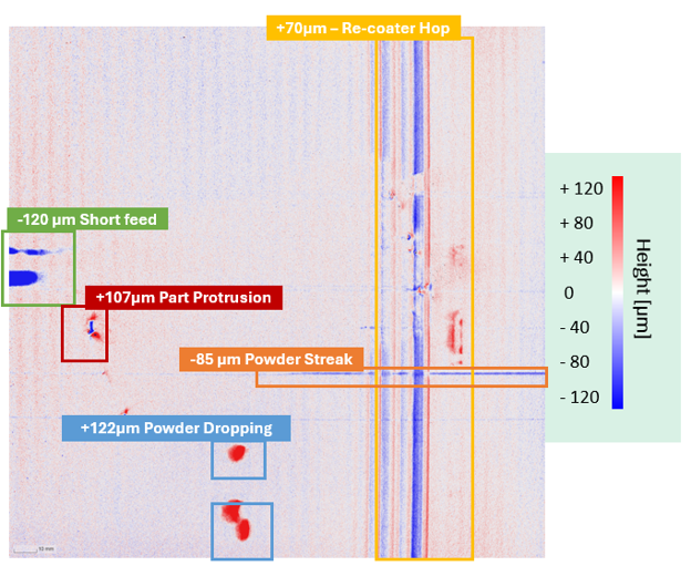
[Fig04. Example Heightmap from Test Build]

[Fig05. Fringe Operator Screenshot of Build – Showing Measurement Tool]
Results: In-Process Measurements vs. Manual Caliper Inspection
Correlation Between Measurement Methods
Across all three technicians, Fringe Operator measurements showed exceptionally strong agreement with manual caliper measurements, with R² values exceeding 0.99 in every case. These results indicate that in-process dimensional measurements can closely replicate conventional post-build inspection outcomes while reducing reliance on manual measurement workflows.

[Fig06. Caliper vs Fringe Operator Measurements: Linear Correlation]
Technician 1: R2 = 0.9989
Technician 2: R2 = 0.9990
Technician 3: R2 = 0.9959
Measurement Variation by Feature Type

[Fig07. Fringe Inspection v Caliper Measurements for Holes]
Hole features exhibited the greatest measurement variation between Fringe Inspection and manual caliper measurements. This was expected, as hole measurements are highly sensitive to caliper positioning and operator interpretation. Even small differences in measurement technique can significantly influence dimensional results, making holes one of the most challenging feature types to inspect consistently.

[Fig08. Fringe Inspection v Caliper Measurements for Pins]
The pin geometries showed improved agreement between Fringe Inspection and caliper measurements. These simpler geometries are less sensitive to operator-dependent variation and easier to evaluate repeatably using manual tools. This is reflected in the results – showing tighter variation between operators, more repeatable measurements, and reduced deviation.

[Fig09. Fringe Inspection v Caliper Measurements for Pins]
Density cube coupons produced the most repeatable measurements overall, exhibiting minimal variation between operators and low deviation between Fringe Operator and caliper measurements. Together with the hole and pin results, this reinforces the relationship between geometry complexity and inspection consistency.
Comparison to CAD Dimensions
Strong agreement between measurement methods does not necessarily mean either method accurately reflects the intended part geometry. To evaluate measurement accuracy, both Fringe Operator and caliper measurements were compared against nominal CAD dimensions using mean absolute error (MAE).

[Fig10. Mean absolute error relative to CAD for each measurement method and feature type.]
 [Fig11. Mean absolute error relative to CAD for holes]
Fringe Operator measurements demonstrated lower error relative to CAD dimensions across all hole sizes when compared with manual caliper measurements.
This result highlights the advantage of Fringe Inspection when evaluating complex geometries and internal features that may be difficult to access or measure consistently using conventional tools. As feature complexity increases, manual measurements become increasingly sensitive to operator technique, tool positioning, and feature accessibility. By leveraging high-resolution heightmaps captured during the build process, Fringe Inspection can provide more consistent dimensional assessment of intricate geometries, enabling improved characterization of features that are challenging to inspect through traditional methods.

[Fig12. Mean absolute error relative to CAD for pins and wall features]
For pin features, Fringe Operator measurements demonstrated lower deviation from CAD dimensions than caliper measurements for the medium and large pins, while higher error was observed for the smallest pin geometries. This trend suggests that Fringe Inspection is capable of accurately characterizing cylindrical features across a range of sizes, but that measurement sensitivity increases as feature dimensions approach the limits of manual edge selection and measurement resolution. Future work will focus on implementing automated edge detection and feature extraction algorithms to reduce operator influence, improve measurement consistency, and enhance accuracy for small-feature geometries.
Wall features exhibited very similar error relative to CAD dimensions for both Fringe Operator and caliper measurements. This result is expected given the relatively simple geometry and accessibility of these features, which can be measured consistently using conventional handheld metrology tools. The close agreement between methods demonstrates that both approaches are capable of accurately characterizing straightforward external geometries, while also providing confidence in the Fringe Inspection measurement workflow for commonly encountered LPBF features.
Why This Matters
The results demonstrate that dimensional validation can begin shifting from a manual, post-build activity to an automated, in-process workflow. Strong agreement with both manual caliper measurements and nominal CAD dimensions indicates that geometry can be assessed during the build process with a high degree of confidence.
Operational Impact
By moving dimensional verification into the manufacturing process, manufacturers can begin identifying geometric variation earlier, reduce dependence on manual inspection activities, and improve measurement consistency across operators.
Depending on existing inspection workflows, this approach has the potential to identify geometric deviations hours or even days earlier than conventional inspection methods while reducing manual inspection labor requirements by approximately 4 hours and $500 per build. For complex internal features that traditionally require CT scanning, in-process geometric validation may also provide a path toward reducing inspection cost and qualification lead time.
Dimensional verification remains a critical step in additive manufacturing quality assurance, but it is often performed using manual inspection methods that are time-consuming, operator-dependent, and only available after the build has completed. This study demonstrates that Fringe Operator measurements strongly correlate with traditional caliper measurements, achieving R² > 0.99 across all three technicians and every feature type evaluated. For the geometries tested, these results indicate that dimensional measurements can be obtained directly from Fringe Inspection data with confidence comparable to conventional manual inspection.
Beyond measurement agreement, the study highlights a broader opportunity to improve additive manufacturing workflows. Manual measurements introduce variability due to operator technique, feature accessibility, and measurement tool placement. By leveraging automated, in-process topographic data, Fringe Inspection provides a more repeatable approach to dimensional assessment while reducing reliance on labor-intensive inspection activities.
Internal Features and CT Scan Reduction
The low deviation from CAD dimensions observed across most feature types further demonstrates that Fringe Operator can be used to validate as-built geometry against the input CAD. This capability is particularly important for additive manufacturing applications where dimensional conformity must be verified before parts proceed to downstream operations or qualification activities.
The results for hole features are especially significant. Additive manufacturing enables complex internal structures, cooling channels, and other geometries that are difficult or impossible to inspect using conventional metrology tools. While technologies such as CT scanning can provide this information, they are often expensive, time-consuming, and impractical for routine production inspection. The strong agreement between Fringe Operator measurements and CAD dimensions suggests that in-process geometric validation can provide manufacturers with a scalable alternative for assessing critical internal and difficult-to-access features.
Enabling In-Process Dimensional Inspection
As additive manufacturing scales toward production, manufacturers require:
- More repeatable measurement methods
- Greater measurement consistency
- Faster geometry validation workflows
- Better process traceability
This is where in-process measurement becomes increasingly valuable.
Rather than waiting until the build is complete, manufacturers can begin evaluating geometry during the build itself, enabling earlier insight into variation and more quantitative dimensional analysis workflows.
The Role of Fringe Inspection™
Fringe Inspection provides quantitative, layer-level measurement data during additive manufacturing production. By measuring geometry directly from heightmaps during the build process, manufacturers gain:
- Earlier visibility into process variation
- Quantitative dimensional data
- Repeatable measurement workflows
- Reduced dependence on manual inspection
This transforms inspection from a purely post-process activity into an integrated part of manufacturing itself.
As additive manufacturing continues scaling toward production, this type of in-process measurement capability will become increasingly important for enabling repeatable quality assurance workflows and production-scale process validation.
Next Steps
This study represents an early step toward expanded geometry measurement capabilities within Fringe Inspection.
Phase3D will continue evaluating Fringe Operator measurements against additional ex-situ measurement methods as part of broader geometry comparison and measurement analysis development.
Future work will focus on:
- Expanded automated geometry recognition
- Additional feature analysis
- Broader comparison across inspection modalities
- Increased dimensional validation capabilities
Conclusion
This study demonstrated exceptionally strong agreement between Fringe Operator measurements and traditional caliper measurements across multiple operators and feature types. Correlation coefficients exceeding R² > 0.99 were observed for all technicians and every geometry evaluated, indicating that Fringe Inspection can provide dimensional measurements consistent with established inspection methods.
At the same time, the results highlighted several limitations associated with manual inspection workflows. Measurement variability increased for more complex geometries, particularly holes and features that are more difficult to access using conventional metrology tools. In these cases, Fringe Operator measurements frequently exhibited lower deviation from CAD dimensions than manual measurements, demonstrating the value of in-process measurement for evaluating complex additive manufacturing geometries.
The hole feature results were particularly noteworthy, as they illustrate the potential for Fringe Inspection to support validation of internal structures and other challenging geometries that are traditionally difficult to inspect without advanced methods such as CT scanning. By capturing dimensional information during the build process itself, Fringe Inspection provides earlier visibility into geometric outcomes and enables verification before parts reach downstream inspection stages.
Overall, this study demonstrates that quantitative, in-process dimensional measurements obtained from Fringe Inspection can closely correlate with traditional physical inspection methods while providing significant workflow advantages. By moving dimensional verification into the manufacturing process, manufacturers can gain earlier visibility into geometry, reduce inspection burden, and support more scalable, data-driven quality assurance. As additive manufacturing production volumes continue to increase, this approach offers a practical path toward faster qualification workflows and more efficient production-scale validation.

Share: