Spatter is one of the most persistent challenges in metal additive manufacturing (AM), often leading to out-of-spec surface roughness, high porosity, and part failures. Traditional monitoring approaches, like high-speed cameras and AI-based image analysis, can’t provide quantitative, traceable data. They rely on subjective interpretation and massive training datasets, offering little in the way of calibrated measurement.
At Phase3D, we set out to prove that a different approach, Fringe Inspection, can deliver measurable, repeatable insights into spatter formation and its downstream effects on part quality.
The Challenge
In laser powder bed fusion (PBF), spatter can cause:
-
Excess surface roughness (often correlating to part porosity)
-
High internal porosity
-
Mechanical testing failures, including reduced ductility and fatigue life
These issues are difficult to detect during a build. Most in-situ monitoring systems rely on camera-based image analysis, which cannot provide true unit-based measurements or identify defects with micron-level accuracy.
The Experiment
To evaluate the effectiveness of Fringe Inspection in detecting and quantifying spatter, Phase3D conducted an experimental build using 17-4PH stainless steel at AMIST.
-
Build layout: 144 individual density coupons in a 4x4 array across 9 regions.
-
Parameter sets:

-
Set 1: Standard EOS 17-4PH parameters
-
Set 2: +5% higher energy density
-
Scan order: Against the gas flow and recoater direction, to ensure part-to-part interaction of spatter particles. The scan direction alternated between 0° and 90°, with a large stripe width to minimize any effects from reflective surfaces.
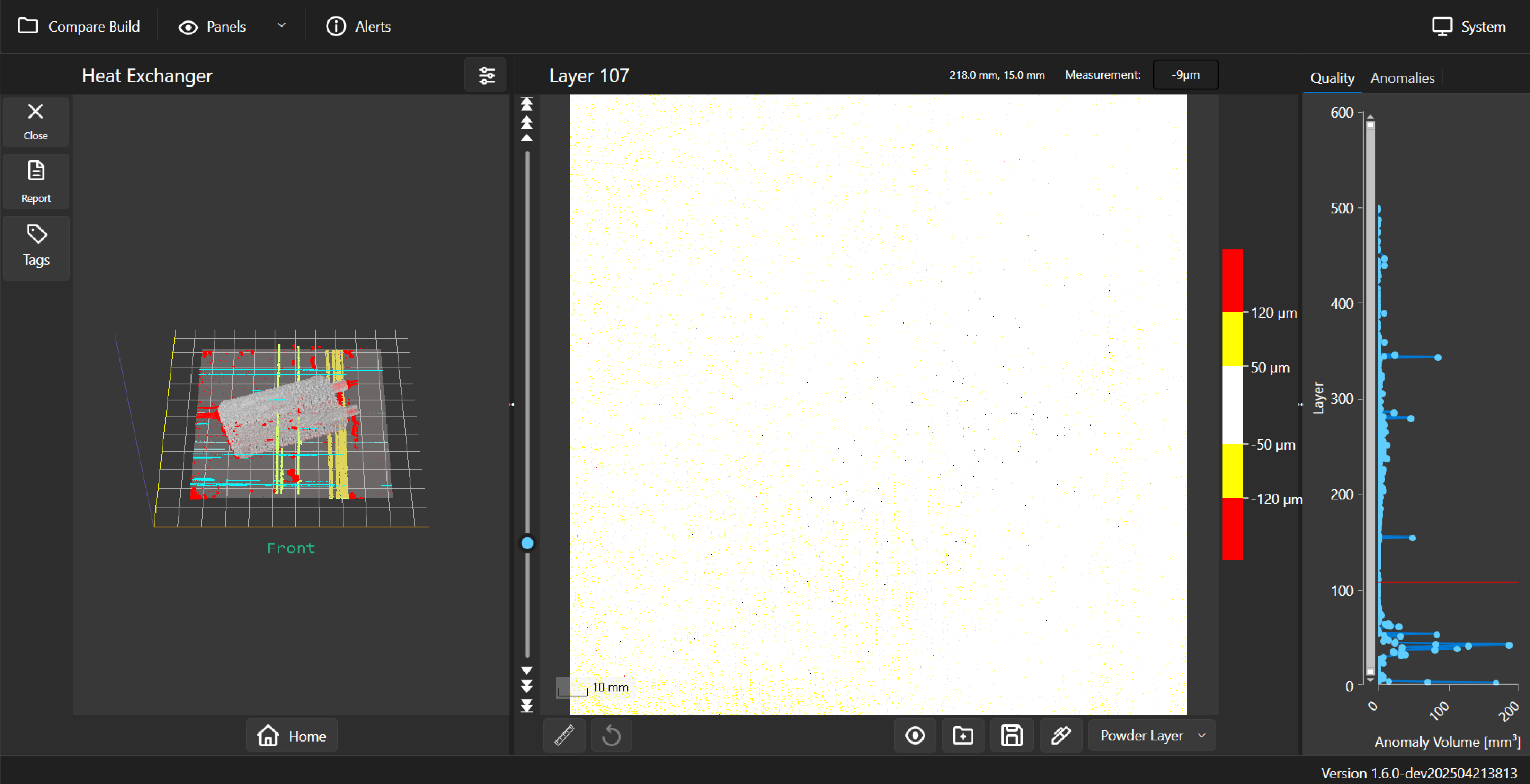
Fringe Inspection captured metrology-grade heightmaps of each layer to calculate surface roughness and identify spatter particles.

Measurement Methodology
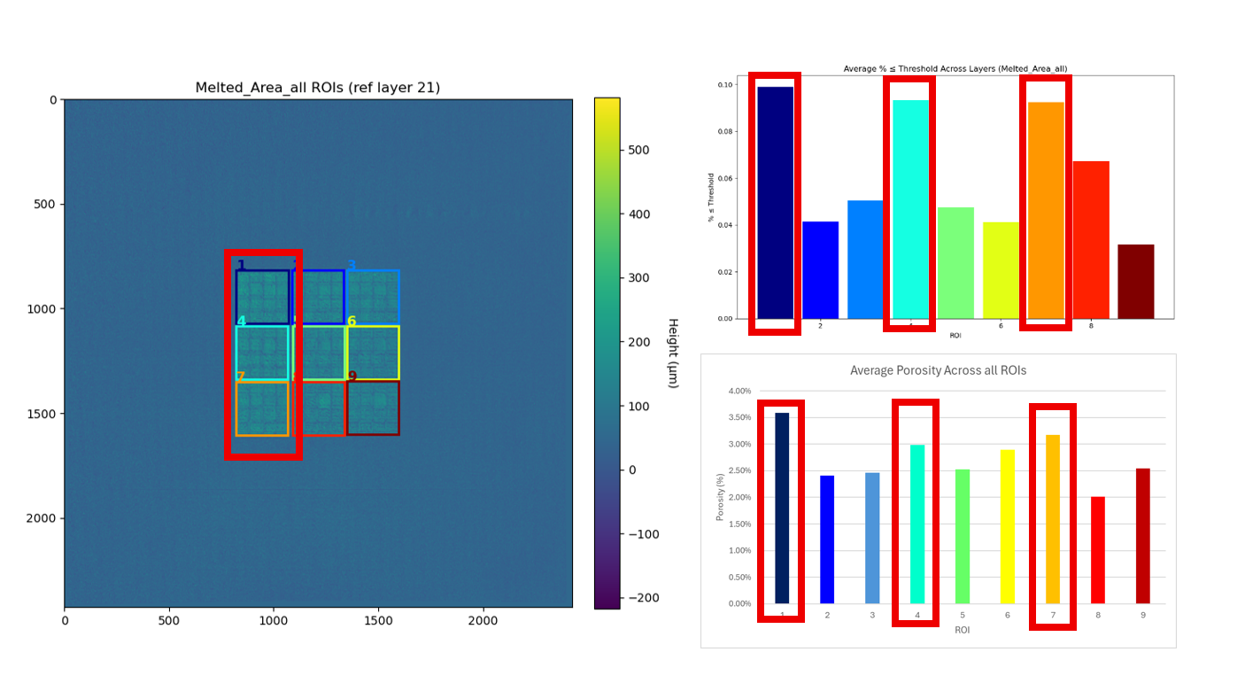
Each of the 9 4x4 arrays of specimens are regions of interest (ROI).
Each ROI was analyzed for:
-
Surface roughness (Ra): Quantified from the heightmap data
where

-
Spatter particles: Defined as ≥75μm over the power area, and ≥50μm over the melted are

For all metrics, the layer thickness channel was used to eliminate any effects from gaussian smoothing. During post-print inspection, Archimedes density testing was performed to determine the porosity of the samples.
Results
1. Over Part: Surface Roughness
The left-hand side of the build showed significantly worse surface roughness, confirming reduced gas flow effectiveness and spatter accumulation. Additionally, these ROIs have higher probability of seeing spatter particles from nearby parts, further increasing the surface roughness.
Fringe Inspection data validated that roughness increases as gas flow efficiency decreases.

2. Over Part: Spatter Particles
Regions with higher roughness also had greater spatter particle density, again aligning with the theory that spatter would increase as gas flow effectiveness decreased.

3. Over Powder: Surface Roughness & Spatter Particles
As expected, the region that experiences a decrease in gas flow (the bottom-left-hand corner) shows the worst surface roughness and the highest amount of spatter particles. Additionally, spatter from the parts that were ineffectively removed by the gas flow would likely land in this region.

4. Porosity vs. Surface Roughness
Regions of Interest (ROIs) with higher surface roughness showed a clear correlation with increased porosity. The data separated into two distinct groups, areas with low surface roughness and low porosity, and areas with high surface roughness and high porosity.
One exception, ROI 8, demonstrated high surface roughness but also elevated porosity. This may indicate that the higher energy density used in this region counteracted the negative effects of reduced gas flow.

5. Porosity vs. Spatter Count
A similar trend was observed between spatter particle count and porosity. ROIs with higher spatter counts exhibited corresponding increases in porosity, again forming two distinct groups, low spatter/low porosity and high spatter/high porosity.
As with the roughness correlation, ROI 8 stood out as an outlier, likely due to the compensating effects of the higher energy density parameter.

Key Takeaways
- Fringe Inspection™ identified and quantified spatter formation across the build area.
- The data correlated directly with post-build porosity, linking in-situ measurements to final part quality.
- No AI, machine learning, or large training datasets required. Only calibrated, traceable measurements.
- Measurements revealed “no-build zones” and gas flow inefficiencies that impact part reliability.
What’s Next
Phase3D is expanding this research to:
- Conduct mechanical testing of additional types of coupons to correlate the spatter metrics directly to changes in part performance.
- Correlate spatter metrics/large-measured spatter particles to porosity found in CT scans.
- Test spatter detection with a higher resolution Fringe Inspection system.
By quantifying surface conditions in real time, Fringe Inspection helps manufacturers understand the true impact of spatter, and move one step closer to predictable, certifiable metal AM.

Share: